|
|
|
|
|
The most common models are Air Storage and Direct Delivery. Below are illustrations of their typical operating principals.
Pneumatic Ejectors will be built to handle the conditions and environment of you application.
|
|
|
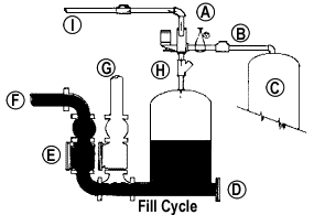
Ejector Air Storage System
- B - Check Valve to prevent back flooding in event of power failure.
- C - Air storage tank
- D - Clean out
- E - Sewage flows through inlet to fill ejector
- F - Inlet
- G - Discharge
- H - "Y" type strainer
- I - Air vent to manhole
|
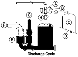 |
- B - Pressure reducing valve
- C - Air storage tank
- D - Sensing device energized when ejector fills to capacity, energizing solenoid valve and activating time delay to control duration of cycle
- E - Inlet check closed to prevent back flow
- F - Inlet
- G - Discharge
- H - "Y" type strainer

|
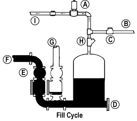 |
Ejector Direct Delivery System
- B - Air line from compressor
- C - Air storage tank
- D - Clean out
- E - Sewage flows through inlet to fill ejector
- F - Inlet
- G - Discharge
- H - "Y" type strainer
- I - Air vent line to man hole with check valve to prevent back flooding
|
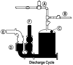 |
- B - Compressed air to flush ejector
- C - Sensing device energizes when ejector fills to capacity, closing solenoid, starting air compressor & activating time delay to control duration of cycle
- D - Inlet check closed to prevent back flow
- E - Inlet
- F - Discharge
|
|
Home | About Us | Products | Facilities | Contact Info | Reps List | News Releases | Career Center
Sewage Stations | Access Doors and Hoists | Tanks | Parts | Controls | Clean Water Systems | WEM
|